
Thermocouple Temperature Measurement Principle and Workflow Explained | From Basics to Industrial Applications
In the field of industrial temperature measurement, thermocouples are widely used in metallurgy, chemical processing, power generation, and manufacturing industries due to their simple structure, fast response, and ability to withstand extreme environments. This article provides a comprehensive and optimized explanation of thermocouple principles, working processes, structure, and applications, helping you fully understand this essential temperature sensing technology.
1. What is a Thermocouple? Core Concept of Temperature Measurement
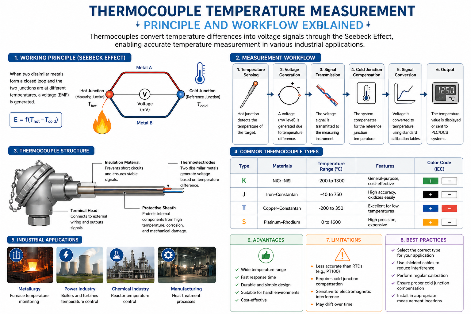
A thermocouple is a temperature sensor based on the “thermoelectric effect.” It consists of two different conductive materials (metals or semiconductors). When these materials are joined to form a closed circuit and a temperature difference exists between the two junctions, an electromotive force (EMF) is generated. This phenomenon is known as the Seebeck Effect.
In simple terms:
👉 Temperature difference → Voltage → Temperature reading
2. Thermocouple Working Principle (Key SEO Section)
1. Seebeck Effect
When two dissimilar metals (A and B) form a circuit and their junctions are at different temperatures (T1 ≠ T2), a voltage (E) is generated. The magnitude of this voltage is a function of the temperature difference.
👉 Formula:
E = f(Thot − Tcold)
This is the fundamental principle behind thermocouple temperature measurement.
2. Hot Junction and Cold Junction
- Hot Junction (Measuring Junction): Placed in the medium being measured
- Cold Junction (Reference Junction): Located at the instrument side
Cold junction compensation is essential to ensure accurate readings.
3. How Thermoelectric Voltage is Generated
When the temperature at the hot junction increases, electrons in the two metals behave differently due to their material properties. This creates a potential difference. As the temperature changes, the voltage changes accordingly.
👉 Key Insight:
Thermocouples measure temperature difference, not absolute temperature.
3. Thermocouple Measurement Workflow (Step-by-Step)
Step 1: Temperature Sensing
The hot junction is exposed to the target medium and detects temperature changes.
Step 2: Voltage Generation
A thermoelectric voltage (in millivolts) is produced due to the temperature difference.
Step 3: Signal Transmission
The voltage signal is transmitted through wires to a measuring instrument.
Step 4: Cold Junction Compensation
The system compensates for the cold junction temperature automatically.
Step 5: Signal Conversion
The voltage is converted into temperature using standard calibration tables (e.g., Type K, Type J).
Step 6: Output Display
The temperature is displayed or transmitted to PLC/DCS systems for control.
4. Structure of a Thermocouple
1. Thermoelectrodes
Made of two different metals (e.g., Type K: Nickel-Chromium / Nickel-Silicon)
2. Insulation Material
Prevents short circuits and ensures signal stability
3. Protective Sheath
Protects against corrosion, high temperature, and mechanical damage
4. Terminal Head
Connects to external circuits and outputs signals
5. Common Thermocouple Types
| Type | Materials | Temperature Range | Features |
|---|---|---|---|
| K | NiCr-NiSi | -200~1300°C | General-purpose, cost-effective |
| J | Iron-Constantan | -40~750°C | High accuracy, oxidizes easily |
| T | Copper-Constantan | -200~350°C | Excellent for low temperatures |
| S | Platinum-Rhodium | 0~1600°C | High precision, expensive |
6. Advantages and Limitations
Advantages:
- Wide temperature range (up to 1600°C)
- Fast response time
- Durable and simple structure
- Suitable for harsh environments
Limitations:
- Lower accuracy than RTDs (e.g., PT100)
- Requires cold junction compensation
- Susceptible to electromagnetic interference
- Drift over long-term use
7. Industrial Applications
Thermocouples are widely used in:
- Metallurgy: Furnace temperature monitoring
- Power industry: Boilers and turbines
- Chemical industry: Reactor temperature control
- Manufacturing: Heat treatment processes
They are often integrated with PLC or DCS systems for automation.
8. Best Practices for Using Thermocouples
- Choose the correct type based on temperature range
- Avoid electromagnetic interference (use shielded cables)
- Perform regular calibration
- Ensure proper cold junction compensation
- Install at appropriate measurement points
9. Conclusion
The essence of thermocouple temperature measurement lies in converting temperature differences into voltage signals, and then translating those signals into accurate temperature readings. Understanding both the principle and workflow is essential for improving measurement accuracy and system reliability.
Post time: 2026-04-27