
Accurate internal process pressure monitoring is a vital requirement across industrial fluid and gas systems. Pressure parameters are typically monitored using dial pressure gauges or electronic pressure transmitters. Serving as integral safety components in industrial facilities, these devices trigger warnings whenever pressure levels deviate above or below established setpoints ($P_{\text{high}}$ / $P_{\text{low}}$), protecting both process quality and personnel safety.
However, when pressure transmitters fail to operate as expected, unmitigated process risks can escalate rapidly. Below are the five primary causes of pressure sensor failures, their diagnostic symptoms, and practical preventive measures.
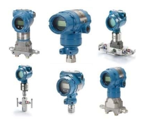
5 Common Causes of Pressure Transmitter Failures
1. Mechanical Vibration
Mechanical vibration is a leading cause of pressure instrument degradation in processing plants. Vibration impacts accuracy in two distinct ways: it makes physical dial pointers erratic to read, and continuous cyclic stress can fatigue delicate mechanical link assemblies.
-
Signs of Vibration Damage:
-
Pointers detaching or dropping due to severe oscillation.
-
A dust-like halo inside the gauge window, indicating worn sector gear teeth and pinion assemblies.
-
-
Mitigation Strategy: Install liquid-filled gauge housings (glycerin or silicone oil) to dampen movement, or choose direct-drive pressure instruments with minimized moving internal components.
2. Overheating and Thermal Fatigue
Industrial processes operating at elevated temperatures can overheat pressure sensing elements. Thermal strain directly weakens Bourdon tubes, internal strain gauges, and piezoresistive diaphragms.
-
Signs of Overheat Damage:
-
Melted dial faces, windows, or transmitter junction boxes caused by extreme process media heat.
-
Discolored housing or yellowed fill fluid when installed too close to superheated gas or liquid lines ($T > T_{\text{max}}$).
-
-
Mitigation Strategy: Select pressure transmitters rated for high ambient and media temperatures. For extreme thermal applications, always retrofit the sensor with a cooling element, impulse line loop, or remote diaphragm seal.
3. Pressure Spikes (Overpressure Events)
Pressure spikes occur when process pressure surges rapidly beyond the transmitter’s Maximum Allowable Working Pressure ($\text{MAWP}$). These sudden hydraulic shocks ($P_{\text{spike}} \gg P_{\text{rated}}$) cause permanent mechanical deformation.
-
Signs of Pressure Spike Damage:
-
Broken or missing dial stop pins.
-
Bent, chipped, or severely misaligned pointers jammed against the stop pin.
-
Zero-point shift or offset error in digital output signals ($4\text{–}20\text{ mA}$).
-
-
Mitigation Strategy: Install inline overpressure protectors or snubbers. These safety valves automatically isolate the sensing element when pressure exceeds pre-set threshold limits.
4. Media Corrosion
Industrial systems often handle aggressive acids, alkalis, and corrosive solvents. Direct contact between incompatible process media and the transmitter’s wetted parts leads to rapid material degradation.
-
Signs of Corrosion Damage:
-
Visible pitting, rust, or flaking on process connections, diaphragms, or instrument enclosures.
-
Discoloration of the stainless steel housing or liquid fill leaking from compromised seals.
-
-
Mitigation Strategy: Deploy diaphragm seals fabricated from corrosion-resistant alloys (such as Hastelloy C-276, Tantalum, or Monel) to isolate aggressive fluids from the sensing element.
5. High-Frequency Pulsation
Pulsation refers to rapid, continuous pressure oscillations often caused by positive displacement pumps or reciprocating compressors. Pulsation accelerates mechanical wear and introduces signal noise into process control loops.
-
Signs of Pulsation Damage:
-
Rapidly fluttering or erratic pointer movement.
-
Loose, sheared, or bent pointer needles in extreme cyclic fatigue scenarios.
-
-
Mitigation Strategy: Combine liquid-filled instrument housings with inline flow restrictors (snubbers) or digital damping functions inside the transmitter firmware to smooth out pressure surges.
Failure Diagnosis & Prevention Summary Matrix
| Failure Cause | Primary Symptom | Diagnostic Indicator | Recommended Preventive Action |
| Mechanical Vibration | Unstable readings | Sector gear wear dust, detached pointer | Liquid-filled gauge or direct-drive sensor |
| Overheating | Drift / Calibration shift | Discolored dial/fill fluid, melted housing | Cooling siphon, impulse tube, or diaphragm seal |
| Pressure Spikes | Permanent zero shift | Bent pointer, damaged diaphragm element | Overpressure protector / Pressure snubber |
| Corrosion | Sensor leak / Failure | Housing discoloration, pitted metal joints | Chemical diaphragm seal (Hastelloy/Tantalum) |
| Pulsation | Signal noise / Flutter | Rapid needle vibration, fatigue failure | Restriction orifice / Electronic signal damping |
Post time: 2026-08-18